3 Input 7 Segment Display Truth Table / Bcd To Seven Segment Display Digital Electronics
For example, the and truth table above can be generalized to three inputs: Patent 1,126,641), when carl kinsley invented a method of telegraphically transmitting letters and numbers and having them printed on tape in a segmented format.in 1908, f.

Showing students that karnaugh maps are really nothing more than truth tables in disguise helps them to more readily learn this powerful new tool.
Decoding is essential in applications like data multiplexing, memory address decoding, and 7 segment display. The diagram below shows the led segment patterns for each digit. There are seven leds present in one unit of the seven segment whose combination is used to make numeral or special characters according to the use. Patent 1,126,641), when carl kinsley invented a method of telegraphically transmitting letters and numbers and having them printed on tape in a segmented format.in 1908, f. Add the resistor of 220 ohms at each input pins. Each logic gate follows a truth table that gives the possible combinations of input and the respective obtained output. The best example of decoder. 24.02.2012 · table i truth table for common cathode type bcd to seven segment decoder this table indicates the segments which are to be driven high to obtain certain decimal digit at the output of the seven segment display. The resistors will lower down the voltages but the value 220ohm is only for 5v output devices. Hope you have used calculators and it is our next example that depicts the combinations of logic gates. The increase in voltage will lead to an increase in resistors. As we know that, seven segment devices display numbers according to control signal pattern and their respective led segments turn on and turn off pattern. Showing students that karnaugh maps are really nothing more than truth tables in disguise helps them to more readily learn this powerful new tool.
The increase in voltage will lead to an increase in resistors. 24.02.2012 · table i truth table for common cathode type bcd to seven segment decoder this table indicates the segments which are to be driven high to obtain certain decimal digit at the output of the seven segment display. One or more such units … The resistors will lower down the voltages but the value 220ohm is only for 5v output devices. However, it is to be noted that in the case of common anode type, the only change will be to interchange ones and zeros on the table. Showing students that karnaugh maps are really nothing more than truth tables in disguise helps them to more readily learn this powerful new tool.

There are seven leds present in one unit of the seven segment whose combination is used to make numeral or special characters according to the use.
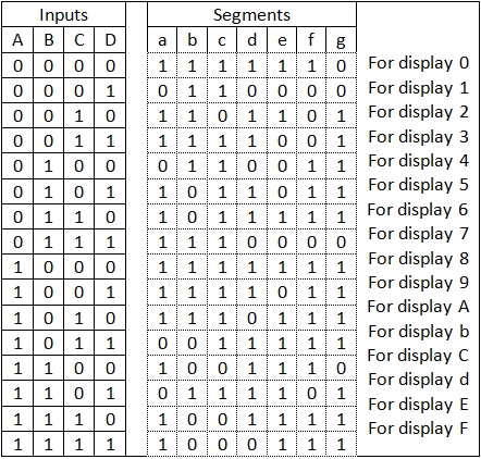
24.02.2012 · table i truth table for common cathode type bcd to seven segment decoder this table indicates the segments which are to be driven high to obtain certain decimal digit at the output of the seven segment display. Add the resistor of 220 ohms at each input pins. The diagram below shows the led segment patterns for each digit. As we know that, seven segment devices display numbers according to control signal pattern and their respective led segments turn on and turn off pattern. Showing students that karnaugh maps are really nothing more than truth tables in disguise helps them to more readily learn this powerful new tool. The best example of decoder. The resistors will lower down the voltages but the value 220ohm is only for 5v output devices. One or more such units … Complete the following karnaugh map, according to the values found in the above truth table: Decoding is essential in applications like data multiplexing, memory address decoding, and 7 segment display. For example, the and truth table above can be generalized to three inputs: Patent 1,126,641), when carl kinsley invented a method of telegraphically transmitting letters and numbers and having them printed on tape in a segmented format.in 1908, f. Although we give our input in the form of numbers, this is what happens within the device. Hope you have used calculators and it is our next example that depicts the combinations of logic gates.
However, it is to be noted that in the case of common anode type, the only change will be to interchange ones and zeros on the table. For example, the and truth table above can be generalized to three inputs: One or more such units … As we know that, seven segment devices display numbers according to control signal pattern and their respective led segments turn on and turn off pattern. Add the resistor of 220 ohms at each input pins. Patent 1,126,641), when carl kinsley invented a method of telegraphically transmitting letters and numbers and having them printed on tape in a segmented format.in 1908, f. In the same way, other segments can also be made high.

The diagram below shows the led segment patterns for each digit.
Each logic gate follows a truth table that gives the possible combinations of input and the respective obtained output. Hope you have used calculators and it is our next example that depicts the combinations of logic gates. Complete the following karnaugh map, according to the values found in the above truth table: However, it is to be noted that in the case of common anode type, the only change will be to interchange ones and zeros on the table. The increase in voltage will lead to an increase in resistors. As we know that, seven segment devices display numbers according to control signal pattern and their respective led segments turn on and turn off pattern. Patent 1,126,641), when carl kinsley invented a method of telegraphically transmitting letters and numbers and having them printed on tape in a segmented format.in 1908, f. The diagram below shows the led segment patterns for each digit. One or more such units … Decoding is essential in applications like data multiplexing, memory address decoding, and 7 segment display. The resistors will lower down the voltages but the value 220ohm is only for 5v output devices. Showing students that karnaugh maps are really nothing more than truth tables in disguise helps them to more readily learn this powerful new tool. The best example of decoder. Although we give our input in the form of numbers, this is what happens within the device. 24.02.2012 · table i truth table for common cathode type bcd to seven segment decoder this table indicates the segments which are to be driven high to obtain certain decimal digit at the output of the seven segment display.
3 Input 7 Segment Display Truth Table / Bcd To Seven Segment Display Digital Electronics. Although we give our input in the form of numbers, this is what happens within the device. The diagram below shows the led segment patterns for each digit. Hope you have used calculators and it is our next example that depicts the combinations of logic gates. 24.02.2012 · table i truth table for common cathode type bcd to seven segment decoder this table indicates the segments which are to be driven high to obtain certain decimal digit at the output of the seven segment display. In the same way, other segments can also be made high.
Add the resistor of 220 ohms at each input pins 7 segment display truth table. The diagram below shows the led segment patterns for each digit.

However, it is to be noted that in the case of common anode type, the only change will be to interchange ones and zeros on the table. Add the resistor of 220 ohms at each input pins. 24.02.2012 · table i truth table for common cathode type bcd to seven segment decoder this table indicates the segments which are to be driven high to obtain certain decimal digit at the output of the seven segment display. One or more such units … The diagram below shows the led segment patterns for each digit. Complete the following karnaugh map, according to the values found in the above truth table:

Each logic gate follows a truth table that gives the possible combinations of input and the respective obtained output. Although we give our input in the form of numbers, this is what happens within the device. Add the resistor of 220 ohms at each input pins. One or more such units …

For example, the and truth table above can be generalized to three inputs: One or more such units … 24.02.2012 · table i truth table for common cathode type bcd to seven segment decoder this table indicates the segments which are to be driven high to obtain certain decimal digit at the output of the seven segment display. The resistors will lower down the voltages but the value 220ohm is only for 5v output devices. Add the resistor of 220 ohms at each input pins. Showing students that karnaugh maps are really nothing more than truth tables in disguise helps them to more readily learn this powerful new tool.

For example, the and truth table above can be generalized to three inputs:
Hope you have used calculators and it is our next example that depicts the combinations of logic gates.

However, it is to be noted that in the case of common anode type, the only change will be to interchange ones and zeros on the table.

Complete the following karnaugh map, according to the values found in the above truth table:

Post a Comment for "3 Input 7 Segment Display Truth Table / Bcd To Seven Segment Display Digital Electronics"